
Page 431 - IRSEM_Main Book
P. 431
II. Description of the Scheme
A. Typical layout of the scheme: The Intermediate Block Section between Two Stations is
reffered for easy understanding. The typical layout of the placement of different DPs
and Signals is as follows:
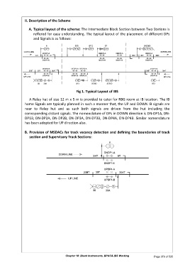
Fig 1. Typical Layout of IBS
A Relay hut of size 12 m x 5 m is provided to cater for RBG room at IB location. The IB
home Signals are typically planned in such a manner that, the UP and DOWN IB signals are
near to Relay hut and as such both signals are driven from the hut including the
corresponding distant signals. The nomenclature of DPs in DOWN direction is DN-DP1A, DN-
DP1B, DN-DP2A, DN-DP2B, DN-DP3A, DN-DP3B, DN-DP4A, DN-DP4B. Similar nomenclature
has been adopted for UP direction also.
B. Provision of MSDACs for track vacancy detection and defining the boundaries of track
section and Supervisory Track Sections:
Chapter 18: Block Instruments, BPAC& IBS Working Page 379 of 535